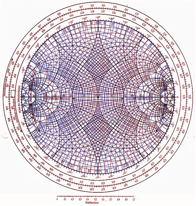

Here, the initial set of lines are termed as constant resistance lines where all are in tangential position each other at the right-hand of the horizontal radius. But when we understand the concept of each line, then the chart is very easy to implement.įor an impedance smith chart, there are two circles that define the information and design of the smith chart which are constant R circles and constant X circles. The pictorial representation of this chart seems to be somewhat typical as there are many lines. This theory corresponds to the basics of smith chart. It is mainly a graphical representation of exhibiting antenna’s impedance corresponding to frequency might be single or few range of points. Here, ‘Z0’corresponds to transmitters impedance, and ‘ZL’ corresponds to load impedance. The mathematical representation of the above statement is that And we all know that impedance is termed as the sum of reactance and resistance and in the same way, the reflection coefficient is also a complex numeral and so represented as load impedance ‘ZL’ and the reference impedance ‘Z0’. BasicsĪs it was already stated that Smith chart exhibits intricate reflection coefficients in the polar form for specific load impedance.
#Colored smith chart series
In the impedance matching operations, it assists in finding out how series or parallel elements influence impedance with minimal effort. This chart is helpful for merging the capability of both the impedance and admittance charts. This is an effective solution where it plots impedance and admittance chart one above the other. The answer to this is the Immittance smith chart. But, in the situation when both the components are implemented, the situation becomes complicated and tricky.

We all have discussed that the impedance smith chart is more useful to deal with series components and the admittance smith chart works well for parallel components. Whereas the tricky part here is mathematical calculation when dealing with parallel elements where the elements are of inductors, transmission lines, and capacitors.Īdmittance Smith Chart Immittance Smith Chart The impedance chart is crucially implemented when working on series loads, all the functionality here is to summate the whole increased impedances. The picture representing impedance smith chart is shown below: Impedance Smith Chart Admittance Smith Chart This impedance of these are the main type where other types are considered as its derivatives. These are generally termed as the usual type of smith charts as they correspond to impedance and functions in an excellent way even with huge loads constructed of many series components where these are the crucial components in the impedance matching and for other RF corresponding operations.

Smith charts are plotted in two dimensions on the intricate reflection coefficient plane and the chart is generally standardized in impedance or admittance or even both through multiple colors in order to differentiate between those parameters and depending on this scaling, these are primarily categorized as three types.


 0 kommentar(er)
